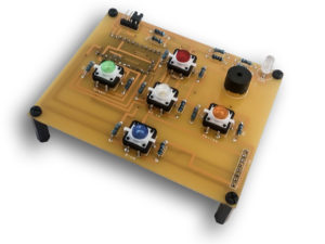
Module - Wrong Sequence - Step by Step Guide
Step 1 - Collect components

1x Pro Mini

1x PCB

16x Resistors

1x RGB LED

Straight pins

Angle pins

5x Tactile LED Button

1x Tone Speaker 12mm

1x Jumper

PCB Names to Components
A1 - ProMini (backside) + Pins (backside)
R1 - 330 Ohm
R2 - 10k Ohm
R3 - 330 Ohm
R4 - 10k Ohm
R5 - 330 Ohm
R6 - 10k Ohm
R7 - 330 Ohm
R8 - 10k Ohm
R9 - 330 Ohm
R10 -10k Ohm
R11 -100 Ohm
R12 -330 Ohm
R13 -330 Ohm
R14 -330 Ohm
R15 -10k Ohm
R16 -10k Ohm
RGB - RGB LED 5mm
Speaker - Speaker Tone Passive 12mm
Address - Angle Pins (4 PCS)
Connector - Straight Pins (backside) 8 PCS
Red - Tactile 12x12 LED Button Red
Green - Tactile 12x12 LED Button Green
White - Tactile 12x12 LED Button White
Yellow - Tactile 12x12 LED Button Yellow
Blue - Tactile 12x12 LED Button Blue

Step 2 - Add 5x Tactile 12x12 LED Button
Add 5x LED tactile buttons, Red on Red, Blue on Blue... on tactile button there is Red dot on Cathode side of LED and must on Right when placing on PCB, if you reverse button LED will not turn on. Solder them.

Step 3 - Add Speaker
Add Speaker Passive Tone 12mm on place where is "Speaker" label. Plus sign must be on right side when looking at PCB. If you reverse Speker it will not make sound. Solder It.

Step 4 - RGB LED
Add 1x RGB LED, one with 4 pins, longest pin is Cathode and is going in square hole on PCB labeled with RGB. Solder it.

Step 5 - Adding Pins
-4x angle pins on "Address" label
-8x straight pin on "Connector" label
-Pins on A1 label from backside as on picture below, few of pins are left floating (not connecting)


Step 6 - Adding resistors
Using table above put resitors in right places. R1 is 330 Ohm, R2 is 10k Ohm... Use Resistor table to get resistor value or you can just use Ohmmeter (if you have one). Solder them.

Step 6 - Solder ProMini with preloaded source code
Solder ProMini on pins, also solder 6x angle pins on ProMini (optional).

Step 7 - Compare images 🙂
If it looks like this, you've done good job 🙂
